Technical Document
Specifications
Brand
WielandSupply Voltage
24V ac/dc
Number of Channels
1
Safety Contacts
2
Function
Safety Monitoring
Reset Method
Manual
Range
safeRELAY
Safety Category ISO 13849-1
2
Safety Category (ISO 13849-1)
2
PL ISO 13849-1
d
PL (ISO 13849-1)
d
SIL IEC 61508
2
SIL (IEC 61508)
2
Terminal Type
Screw
Series
SNO 1012
Width
22.5mm
Depth
91.5mm
Performance Level
d
Length
96.5mm
Country of Origin
Germany
Product details
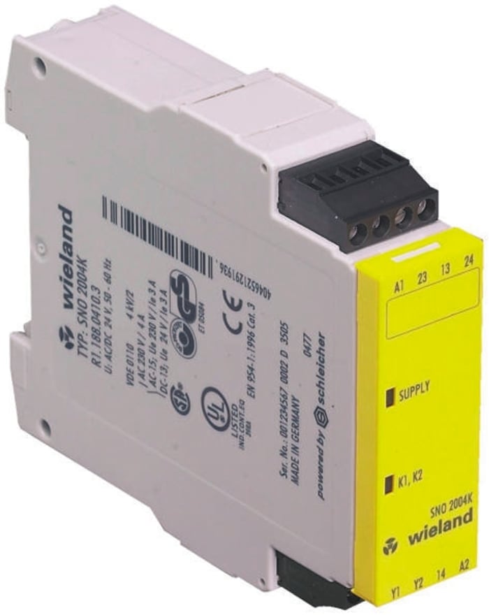
Wieland SNO 1012K Safety Relay
SNO 1012K Safety Relay Function - after the operating voltage (L+/L1) is applied via an unactuated emergency stop button or safety gate contact on A1 and A2, the device can be switched on via a Y1/Y2-connected reset button. When the device is on, the internal relays K1 and K2 are energized and the enabling current paths 13/14 and 23/24 are closed. When the emergency stop button or the safety gate contact is actuated, the current supply of the internal relays is interrupted and the enabling current paths are opened.
Monitoring of E-Stop and Safety Gate applications
Stop Category 0 according to EN 60204-1
Single-channel control
Manual or automatic start
2 enabling current paths
Check of external contactors (EDM)
Compact design
Up to PL d / Category 2 (EN ISO 13849-1)
Up to SILCL 2 (EN 62061)


Stock information temporarily unavailable.
Please check again later.
SR 1,312.36
Each (ex VAT)
SR 1,509.21
Each (inc. VAT)
1
SR 1,312.36
Each (ex VAT)
SR 1,509.21
Each (inc. VAT)
1


Technical Document
Specifications
Brand
WielandSupply Voltage
24V ac/dc
Number of Channels
1
Safety Contacts
2
Function
Safety Monitoring
Reset Method
Manual
Range
safeRELAY
Safety Category ISO 13849-1
2
Safety Category (ISO 13849-1)
2
PL ISO 13849-1
d
PL (ISO 13849-1)
d
SIL IEC 61508
2
SIL (IEC 61508)
2
Terminal Type
Screw
Series
SNO 1012
Width
22.5mm
Depth
91.5mm
Performance Level
d
Length
96.5mm
Country of Origin
Germany
Product details
Wieland SNO 1012K Safety Relay
SNO 1012K Safety Relay Function - after the operating voltage (L+/L1) is applied via an unactuated emergency stop button or safety gate contact on A1 and A2, the device can be switched on via a Y1/Y2-connected reset button. When the device is on, the internal relays K1 and K2 are energized and the enabling current paths 13/14 and 23/24 are closed. When the emergency stop button or the safety gate contact is actuated, the current supply of the internal relays is interrupted and the enabling current paths are opened.
Monitoring of E-Stop and Safety Gate applications
Stop Category 0 according to EN 60204-1
Single-channel control
Manual or automatic start
2 enabling current paths
Check of external contactors (EDM)
Compact design
Up to PL d / Category 2 (EN ISO 13849-1)
Up to SILCL 2 (EN 62061)


